
Arduino
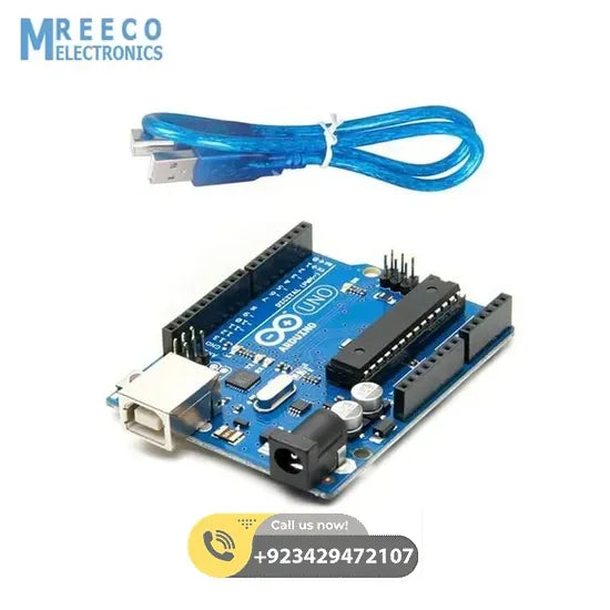
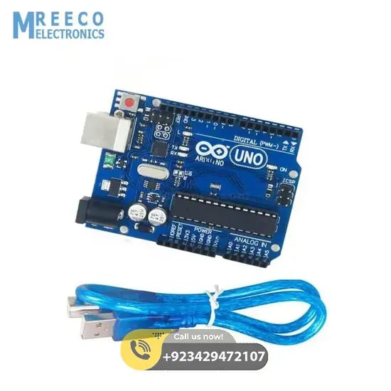
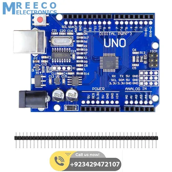
Arduino Uno Price In Pakistan Arduino Kit With USB Cable
Sale priceRs 1,450.00
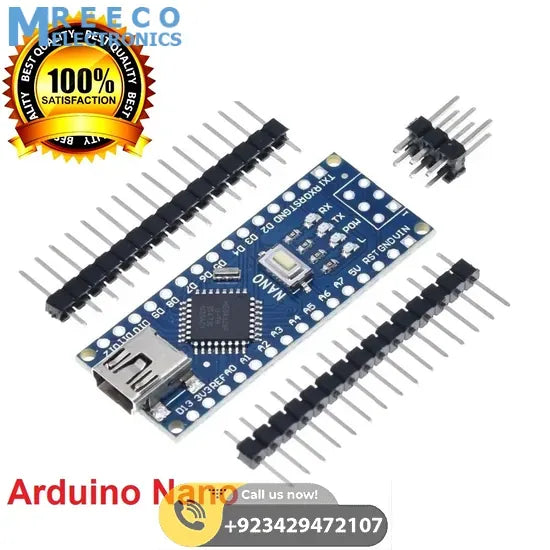
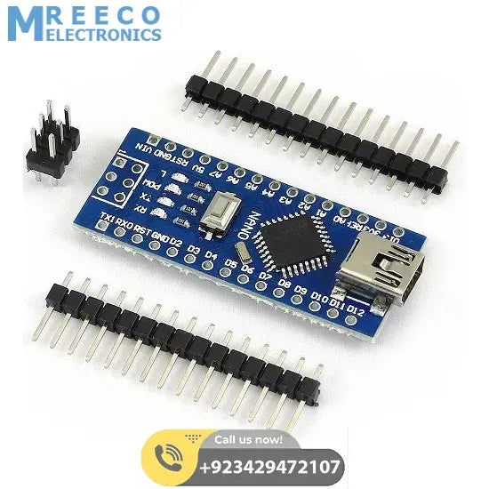
Arduino Nano V3
Sale priceRs 650.00
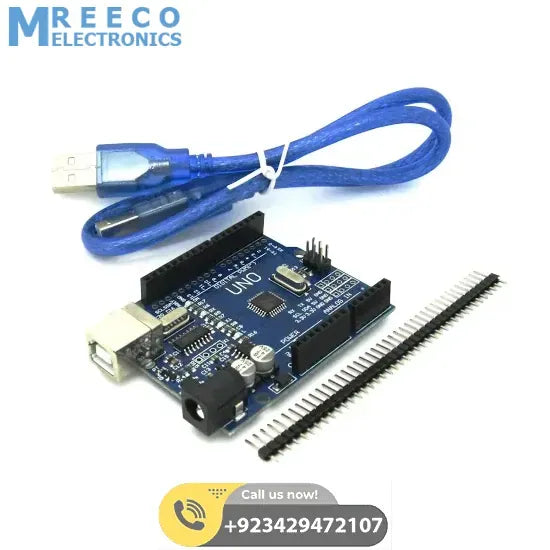
Arduino Uno R3 SMD Board Kit Without USB Cable
Sale priceRs 850.00
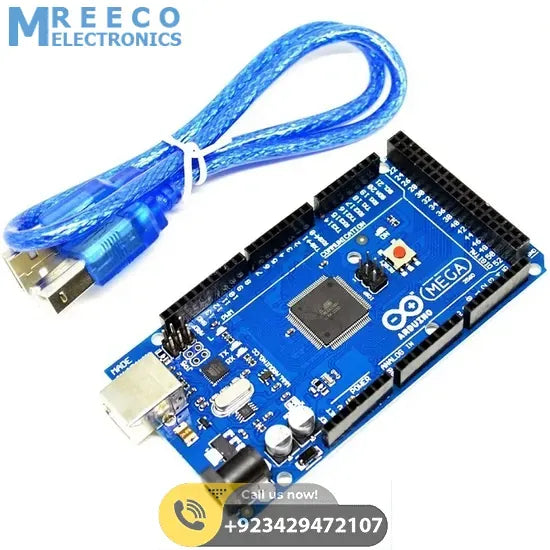
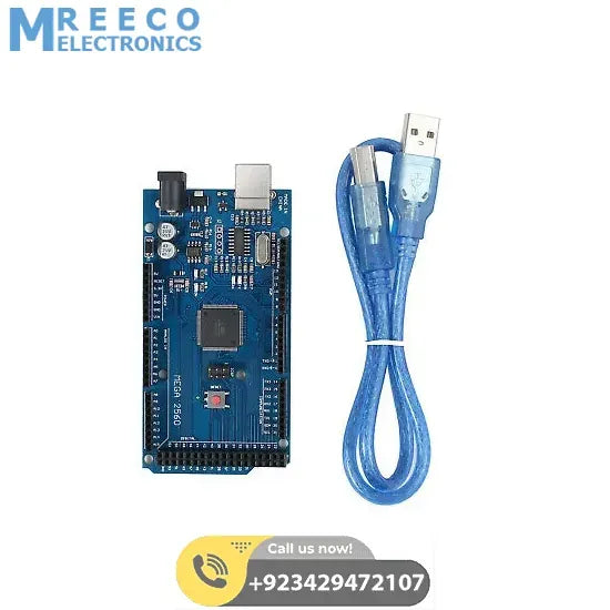
Arduino Mega 2560 R3 In Pakistan
Sale priceRs 3,700.00
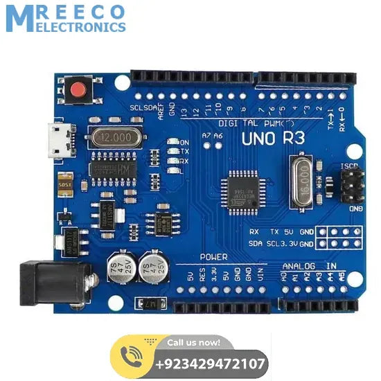
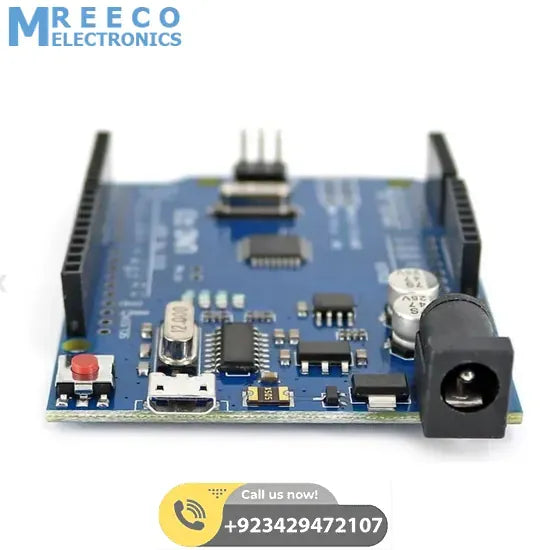
Micro Usb Arduino Uno R3
Sale priceRs 1,550.00
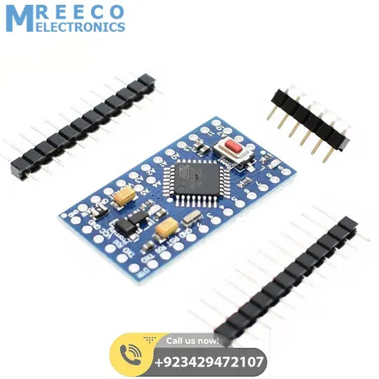
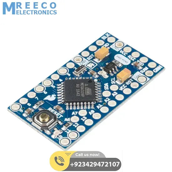
Arduino Pro Mini 3.3V 8Mhz ATMEGA328P in Pakistan
Sale priceRs 1,200.00
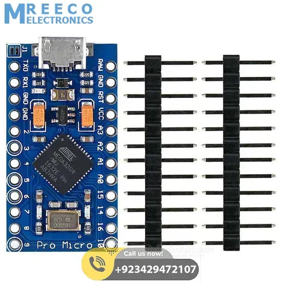
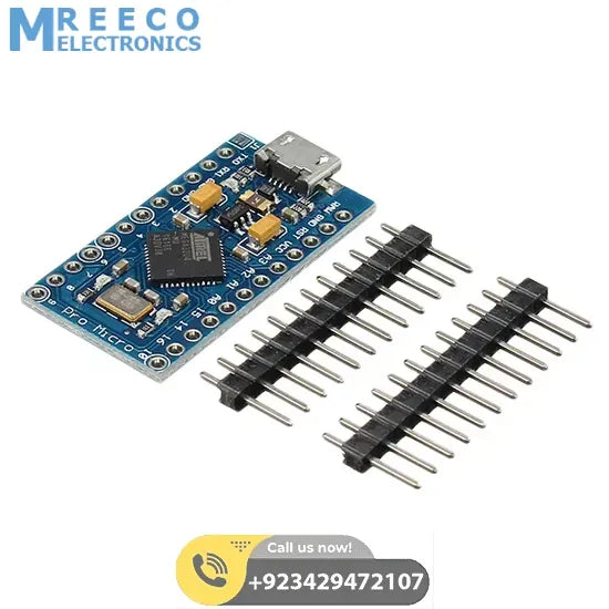
Arduino Pro Micro 5v 16m Atmega32u Rubber Ducky Rubberducky
Sale priceRs 1,250.00
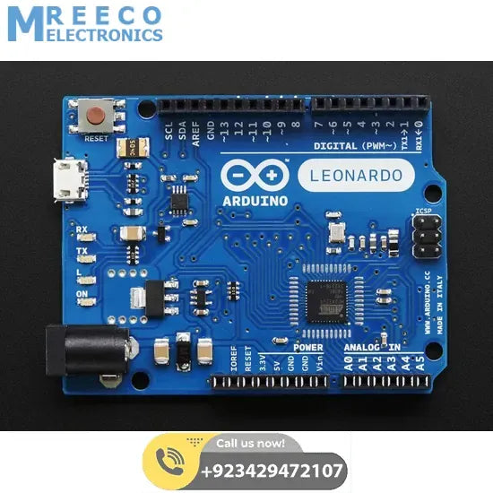
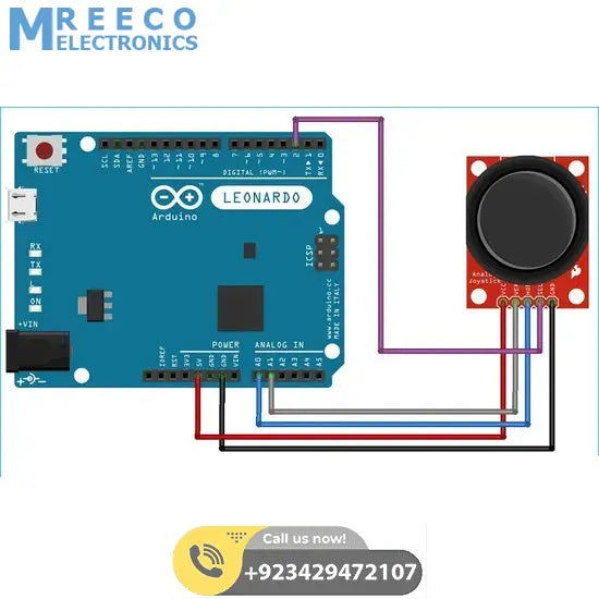
Arduino Leonardo R3 Board – ATmega32u4 Microcontroller, 20 I/O Pins, USB, 16MHz
Sale priceRs 1,550.00
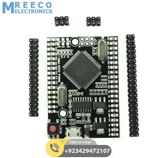
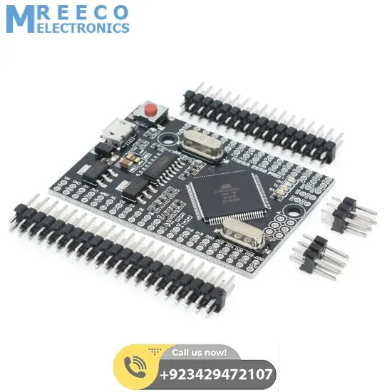
Mega 2560 Pro Mini Embed Ch340g Atmega 2560-16a With Male Pin Headers In Pakistan
Sale priceRs 2,950.00
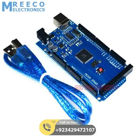
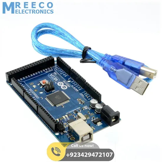
Ch340 Arduino Mega 2560 With Cable In Pakistan
Sale priceRs 3,500.00
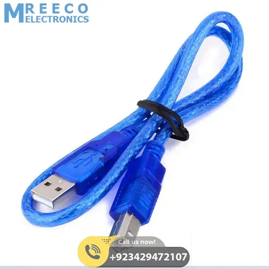

Usb Cable For Arduino Uno Arduino Mega
Sale priceRs 120.00
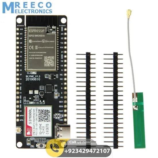
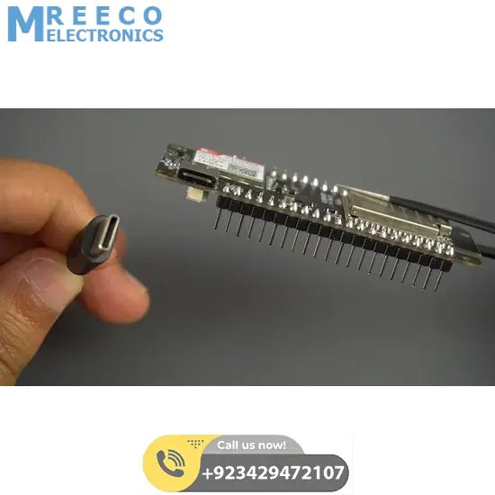
T-Call V1.3 ESP32 SIM800L GSM Module
Sale priceRs 5,000.00
Raspberry Pi
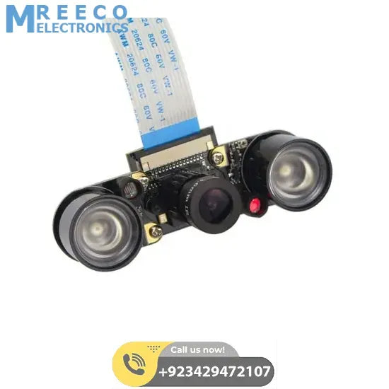
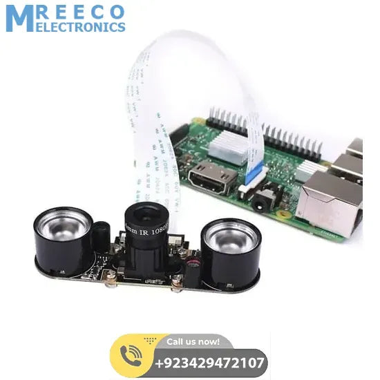
Night Vision 5mp Camera Module For Raspberry Pi With 2 Ir Leds
Sale priceRs 3,900.00
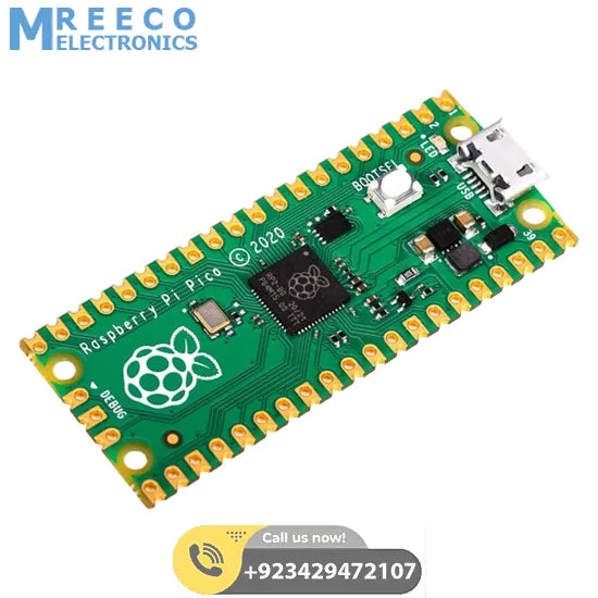
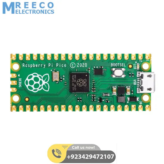
Raspberry Pi Pico Rp2040 Cheap Price In Pakistan
Sale priceRs 1,200.00
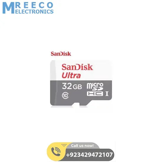

Class 10 Sandisk 32gb Ultra Micro Sd Card For Raspberry Pi
Sale priceRs 1,450.00
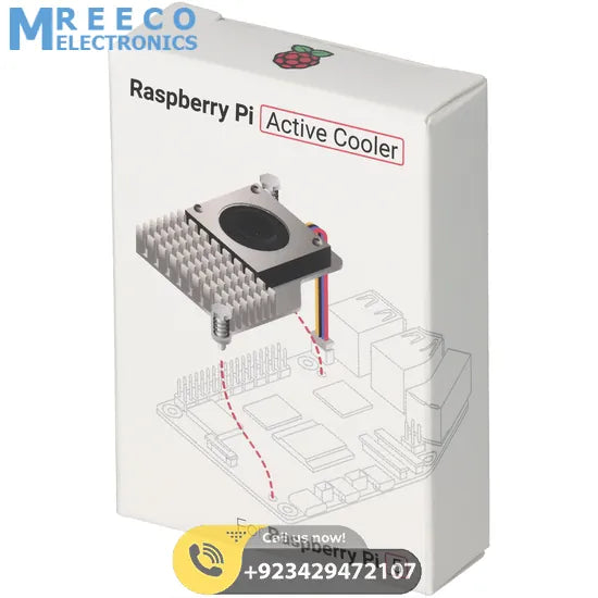
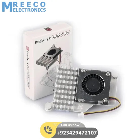
Raspberry Pi 5 Active Cooler with Aluminum Heatsink in Pakistan
Sale priceRs 2,000.00
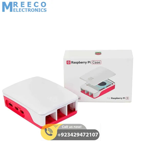
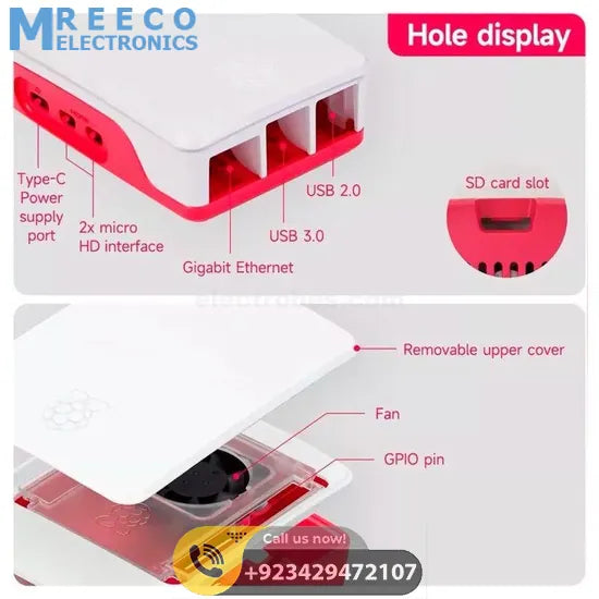
Official Raspberry Pi Case for Raspberry Pi 5, Built-in Cooling Fan, Red/White Color
Sale priceRs 3,000.00
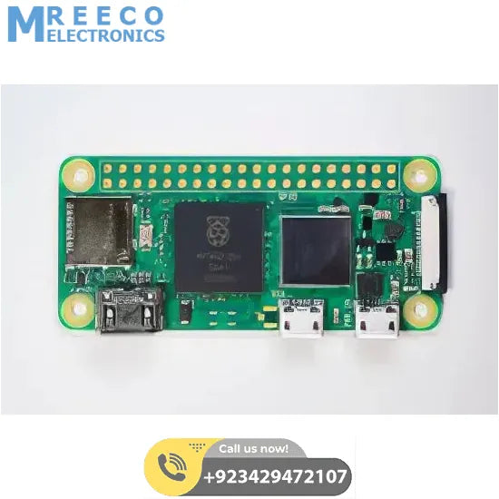

Raspberry Pi Zero 2 W In Pakistan
Sale priceRs 10,000.00
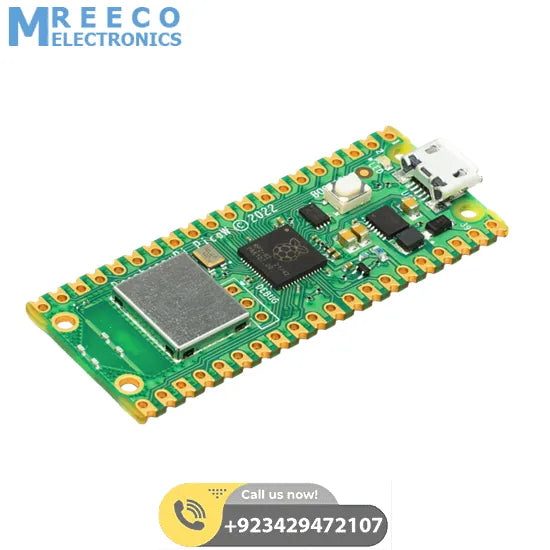
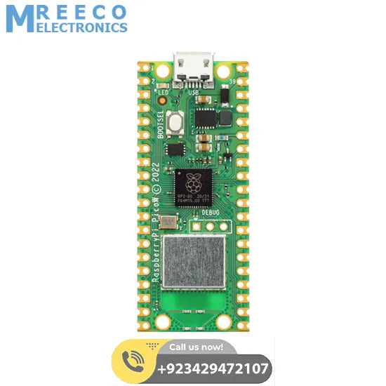
Raspberry Pi Pico W
Sale priceRs 2,700.00
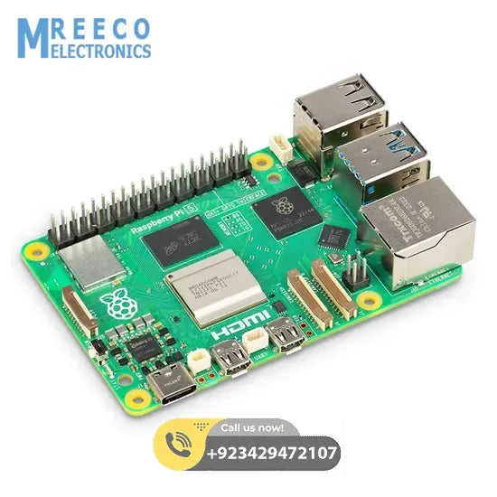
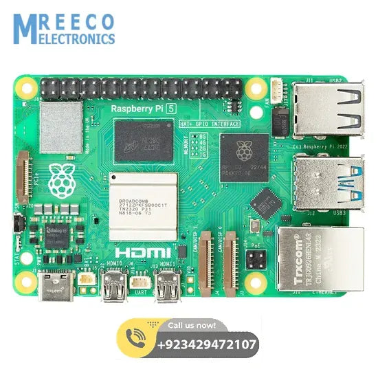
Raspberry Pi 5 4GB In Pakistan
Sale priceRs 23,500.00
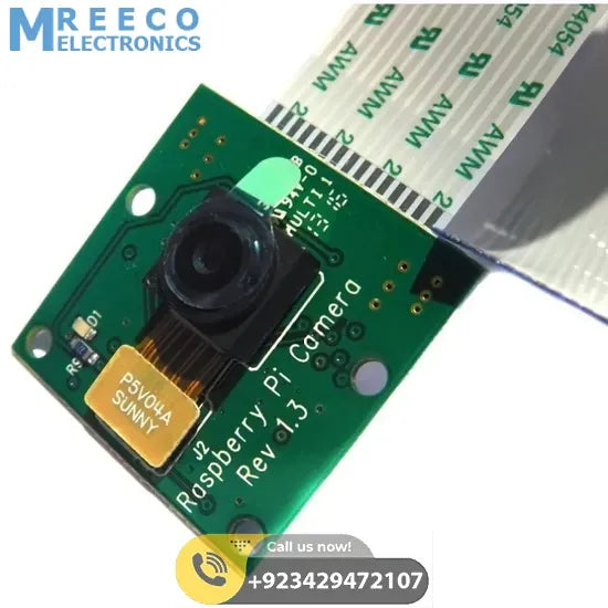
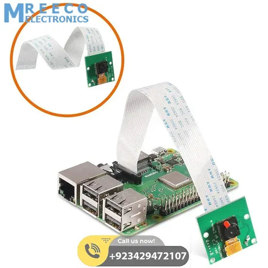
5mp Raspberry Pi Camera Module V1.3 In Pakistan
Sale priceRs 1,500.00
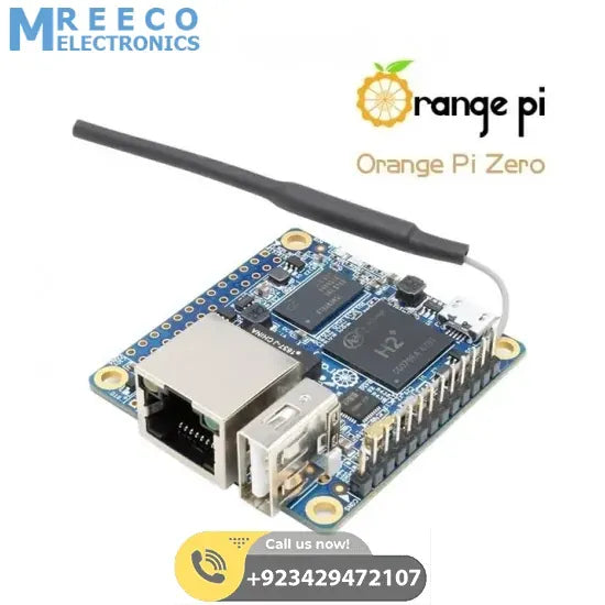
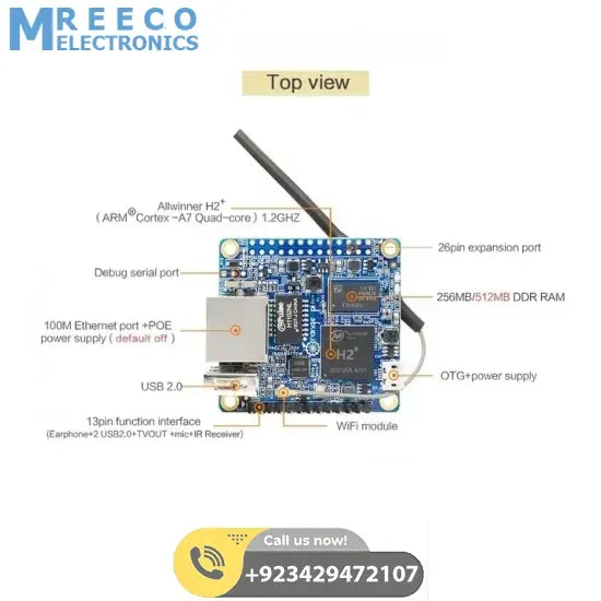
512mb Orange Pi Zero H2 Development Board
Sale priceRs 4,000.00
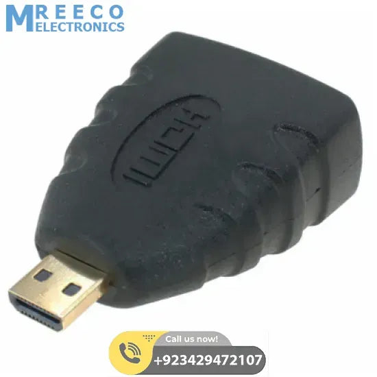
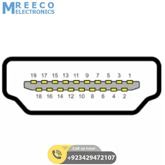
Hdmi Female To Micro Hdmi Male Converter Adapter For Raspberry Pi 4
Sale priceRs 250.00
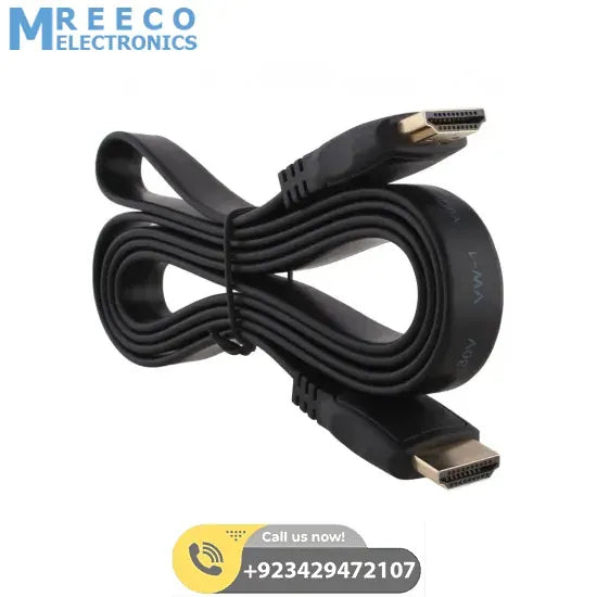
HDMI to HDMI Cable High-Quality HDMI Cable Male to Male Type A To Type A
Sale priceRs 220.00