

Description
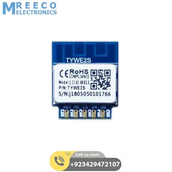
TYWE2S is a low power consumption module with a built-in Wi-Fi connectivity solution. The Wi-Fi Module consists of a highly integrated wireless radio chip ESP8266EX and extra flash which has been programmed with Wi-Fi network protocol and plenty of software examples.TYWE1S also has an 32-bit CPU, 1M byte flash, 50k SRAM and various peripheral resources.
TYWE2S is an RTOS platform, embedded with all the Wi-Fi MAC and TCP/IP protocol function examples, users can customize their Wi-Fi product by using these software examples.
The figure shows the block diagram of the TYWE2S.
Features
- Integrated low power consumption 32-bit CPU, also known as application processor Basic frequency can support both 80MHz and 160MHz Supply voltage range: 3V to 3.6V Peripherals: 5×GPIOs, 1×UART, 1×ADC Wi-Fi connectivity:
- 802.11 b/g/n Channel 1 to 14 @ 2.4GHz Support WPA/WPA2 +20dBm output power in 802.11b mode Support STA/AP/STA+AP operation mode Support Smart Link function for both Android and iOS devices Standby power consumption is less than 0.1 mW (DTIM3) On-board PCB antenna, or IPEX connector for external antenna CE, FCC certified Operating temperature range: -20ºC to 85ºC
Main Application Fields
- Intelligent Building Intelligent home, Intelligent household applications Health care Industrial wireless control Baby monitor Webcam Intelligent bus
Dimensions
and Footprint
Dimensions
TYWE2S has 2 columns of Pins (2* 9). The distance between each Pin is 2mm. Size of TYWE1S: 3 mm(W)* 15mm(L) * 17.3mm(H)
Pin Definition
Pin Number Symbol IO type Function 1 3V3 P Module Power Pin(3.3V) 2 05 I/O GPIO_05 3 GND P Power Reference Ground 4 04 I/O GPIO_04 5 RX I/O UART0_RXD(2) 6 13 I/O GPIO_13 7 TX I/O UART0_TXD(2) 8 AD AI ADC port, 10-bit precision SAR ADC 9 12 I/O GPIO_12 10 RST I/O Hardware reset pin (low level effective, internal pull-up resistance) 11 14 I/O GPIO_14Instructions:P indicates the power pin,I/O means input and output pins,AI represents the analog input pin. RST is just module hardware reset pin, can't clear the WiFi distribution network. (1): This pin can only be used as an ADC port, can not be used as a normal IO port, need to be suspended when not in use. When used to ad an ADC input, the input voltage range is limited to 0~1.0V. (2): UARTO is the user serial port, when the module is powered om, serial port has information output, the user can ignore.
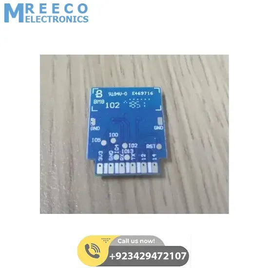
Pin Number Symbol IO type Function - IO4 I/O GPIO_04 - IO13 I/O GPIO_13 - IO2 I/O UART0_TXD(Module information print port) - RST I/O Reset pin - IO5 I/O GPIO_05 - IO0 I/O IO0 participates in the module startup when the module is suspended, the module enters the normal running state.Instructions:I/O means input and output pins. I/O0 is left floating, the module is running normally, IO0 is low level, and the module is in firmware burning state. A test pin is not recommended.
PCB Packaging
MechanicalDimensions
PCB Recommended Package
Package Includes:
1 x Esp 8285 Smart WiFi Module Develop Wireless Networking Intelligent Module