
- Home
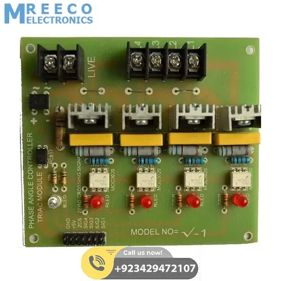
- Arduino 4 Channel Triac Module With Zero Crossing Sensor in Pakistan


China
Arduino 4 Channel Triac Module With Zero Crossing Sensor in Pakistan
Rs 700
Currently sold out
This is 4 Channel Triac Module Module which gives you the ability to make Arduino Ac Dimmer or arduino ac phase angel controller or it can control AC related applications with your Arduino,Raspberry pi, PIC or Any ot...
Ask about this product on WhatsApp- Fast deliveryFree shipping on prepaid orders above Rs. 10,000
- Secure payment100% secure payments by Meezan Bank
- SupportMonday to Saturday, 11:00 AM to 8:00 PM
- ReturnsSee our return and refund policy
Description
This
is
4
Channel
Triac
Module
Module
which
gives
you
the
ability
to
make
Arduino
Ac
Dimmer
or
arduino
ac
phase
angel
controller
or
it
can
control
AC
related
applications
with
your
Arduino,Raspberry
pi,
PIC
or
Any
other
microcontroller.
There
are
four
channels
as
mentioned
in
the
item
description
and
all
channels
can
be
used
same
time.
class='font-size-24
mb-3'>Features:
Comprises
with
MOC3021
Zero
Cross
Phototriac
Driver
optocoupler
and
BT16
Triac
Simplifies
Logic
Control
of
115/240
Vac
Power
Zero
Voltage
Crossing
Signal
dv/dt
of
1500
V/µs
Typical,
600
V/µs
Guaranteed
class='font-size-24
mb-3'>Applications:
Solenoid/Valve
Controls
Temperature
Controls
Lighting
Controls
E.M.
Contactors
Static
Power
Switches
AC
Motor
Starters
AC
Motor
Drives
Solid
State
Relays
Here
is
example
code
and
please
see
video
for
more
details.
//
By
Irfan
Ahmad
#define
DETECT
2
//zero
cross
detect #define
GATE
9
//TRIAC
gate #define
PULSE
500
//trigger
pulse
width
(counts) int
brightness=0;
#include void
setup(void) { pinMode(DETECT,
INPUT);
//zero
cross
detect digitalWrite(DETECT,
HIGH);
//enable
pull-up
resistor pinMode(GATE,
OUTPUT);
//TRIAC
gate
control attachInterrupt(0,zeroCrossingInterrupt,
RISING); Timer1.attachInterrupt(timer1_interrupt);
//
blinkLED
to
run
every
0.15
seconds Serial.begin(9600); } void
loop(void) { int
variable_value
=
analogRead(A0); brightness
=
map(variable_value,
0,
1023,
0,9000); if(brightness>7500)
detachInterrupt(0);
//
disconnect
interrrupt else
attachInterrupt(0,zeroCrossingInterrupt,
RISING);
//
connect
interrupt Serial.println(brightness); delay(100); }
//////////////////////////
voidzeroCrossingInterrupt(){
//zero
cross
detect
interrupt Timer1.initialize(brightness); }
//////////////////////////
///////////// intstate=0; void
timer1_interrupt(void)
//
timer
interrupt
to
triger
gate { if(state==0){state=1;Timer1.initialize(PULSE);digitalWrite(GATE,HIGH);}//
turn
on
gate else
{state=0;Timer1.stop();digitalWrite(GATE,LOW);}
//
turn
off
gate }
//////////////////////////
/////////////////////////class='font-size-24
mb-3'>AC
Phase
Control
One
method
of
controlling
power
to
AC
circuits
uses
a
TRIAC
to
turn
the
power
on
and
off
at
precisely
timed
intervals
that
are
synchronized
with
the
AC
signal.
This
method
is
called
AC
phase
control.
It
is
the
method
used
in
many
light
dimmer
and
heater
power
control
circuits.
class='font-size-24
mb-3'>See
Also
http://playground.arduino.cc/Code/ACPhaseControl
class='font-size-24
mb-3'>Circuit
Using
an
Arduino
microcontroller
with
some
simple
circuitry,
we
can
monitor
the
AC
wave
to
determine
the
proper
time
to
turn
the
power
on
and
off
with
the
TRIAC
The
circuit
consists
of
an
opto-isolated
zero-crossing
detector
and
an
opto-isolated
trigger
circuit
for
the
TRIAC.
The
opto-isolators
are
necessary
to
keep
the
low
voltage
signal
circuits
away
from
the
power
circuits
and
provide
an
appropriate
level
of
safety.
As
with
all
circuits
involving
mains
voltage,
make
sure
you
know
what
you
are
doing.
class='font-size-24
mb-3'>Theory
of
Operation
The
zero-crossing
detection
circuit
provides
a
5V
pulse
every
time
the
AC
signal
crosses
zero
volts.
We
detect
this
with
the
Arduino
and
leverage
interrupts
to
time
the
trigger
circuit
precisely
in
synchronization
with
these
zero-crossing
events.
The
method
for
power
control
is
shown
in
the
diagram
below.
Once
a
zero
crossing
is
detected,
the
TRIAC
remains
off
for
a
controlled
amount
of
time
(t1)
.
The
longer
this
time
is,
the
less
power
the
AC
circuit
receives.
Once
the
“off-time”,
t1
has
elapsed,
the
microcontroller
turns
on
the
TRIAC
by
applying
a
voltage
to
the
gate
(shown
in
red).
Once
turned
on,
the
TRIAC
will
remain
on
even
after
the
gate
voltage
has
been
removed.
It
will
turn
off
if
the
gate
voltage
is
zero
the
next
time
the
AC
wave
crosses
zero.
Because
of
this,
we
do
not
need
to
take
care
to
turn
the
TRIAC
off
when
the
AC
signal
crosses
zero
again.
All
we
need
to
do
is
to
ensure
that
the
TRIAC
gets
turned
off
inside
of
the
period
of
½
wave
(t3).
The
duration
of
the
gate
pulse
(t2)
is
determined
by
a
minimum
requirement
of
the
traic.
If
this
pulse
is
too
short,
the
traic
will
not
fire
Once
the
second
zero
crossing
occurs,
since
there
is
no
voltage
on
the
gate,
the
TRIAC
remains
off
until
triggered
again
in
the
next
½
cycle.
The
net
result
here
is
that
we
“chop”
parts
of
the
wave
out
resulting
in
lower
average
power.
This
is
essentially
how
one
accomplishes
“PWM”
control
of
an
AC
wave.
We
will
be
using
interrupts
and
the
Arduino
timer
to
precisely
control
the
timing
of
the
TRIAC
gate.
To
get
a
feel
for
the
time
intervals,
we
need
to
look
at
the
AC
signal
and
the
Arduino
clock.
The
AC
signal
(in
the
US
anyway)
is
60
Hz.
What
this
means
is
that
the
AC
signal
crosses
zero,
reaches
peak
positive
voltage,
crosses
zero,
reaches
peak
negative
voltage
and
returns
to
zero
60
times
each
second.
The
period
(length
of
time
this
takes)
is
1/60
or
0.01667
seconds
(16.67
milliseconds).
A
half
cycle
(the
time
between
two
zero-crossings)
occurs
in
8.33
milliseconds.
This
is
t3
in
the
figure
above.
The
Arduino
clock
runs
at
16
MHz,
which
is
16,000,000
cycles
per
second:
one
clock
cycle
takes
0.0625
microseconds.
A
single
half
cycle
of
the
60
Hz
AC
signal
contains
133,333
clock
cycles.
This
is
important
because
we
will
be
determining
the
time
intervals
by
clock
counts
in
the
Arduino
code,
not
by
seconds.
There
is
quite
a
bit
of
good
information
on
use
of
interrupts
with
the
Arduino
out
on
the
web
so
I
won’t
cover
that
in
much
detail
here.
Basically
the
way
an
interrupt
works
is
that
when
some
event
happens
(either
internal
or
external
to
the
microprocessor),
the
microprocessor
immediately
stops
what
it
is
doing
to
“service”
the
interrupt.
This
allows
the
microprocessor
to
handle
very
time
sensitive
events
such
as
the
AC
Phase
control
task
here.
HeaterControl.pde
//AC
Control
V1.1 // //
This
Arduino
sketch
is
for
use
with
the
heater
//
control
circuit
board
which
includes
a
zero
//
crossing
detect
function
and
an
opto-isolated
TRIAC. // //
AC
Phase
control
is
accomplished
using
the
internal
//
hardware
timer1
in
the
Arduino // //
Timing
Sequence //
*
timer
is
set
up
but
disabled //
*
zero
crossing
detected
on
pin
2 //
*
timer
starts
counting
from
zero //
*
comparator
set
to
"delay
to
on"
value //
*
counter
reaches
comparator
value //
*
comparator
ISR
turns
on
TRIAC
gate //
*
counter
set
to
overflow
-
pulse
width //
*
counter
reaches
overflow //
*
overflow
ISR
turns
off
TRIAC
gate //
*
TRIAC
stops
conducting
at
next
zero
cross //
The
hardware
timer
runs
at
16MHz.
Using
a //
divide
by
256
on
the
counter
each
count
is
//
16
microseconds.
1/2
wave
of
a
60Hz
AC
signal //
is
about
520
counts
(8,333
microseconds). #include
#include
#define
DETECT
2
//zero
cross
detect #define
GATE
9
//TRIAC
gate #define
PULSE
4
//trigger
pulse
width
(counts) int
i=483; void
setup(){
//
set
up
pins
pinMode(DETECT,
INPUT);
//zero
cross
detect
digitalWrite(DETECT,
HIGH);
//enable
pull-up
resistor
pinMode(GATE,
OUTPUT);
//TRIAC
gate
control
//
set
up
Timer1
//(see
ATMEGA
328
data
sheet
pg
134
for
more
details)
OCR1A
=
100;
//initialize
the
comparator
TIMSK1
=
0x03;
//enable
comparator
A
and
overflow
interrupts
TCCR1A
=
0x00;
//timer
control
registers
set
for
TCCR1B
=
0x00;
//normal
operation,
timer
disabled
//
set
up
zero
crossing
interrupt
attachInterrupt(0,zeroCrossingInterrupt,
RISING);
//IRQ0
is
pin
2.
Call
zeroCrossingInterrupt
//on
rising
signal }
//Interrupt
Service
Routines void
zeroCrossingInterrupt(){
//zero
cross
detect
TCCR1B=0x04;
//start
timer
with
divide
by
256
input
TCNT1
=
0;
//reset
timer
-
count
from
zero } ISR(TIMER1_COMPA_vect){
//comparator
match
digitalWrite(GATE,HIGH);
//set
TRIAC
gate
to
high
TCNT1
=
65536-PULSE;
//trigger
pulse
width } ISR(TIMER1_OVF_vect){
//timer1
overflow
digitalWrite(GATE,LOW);
//turn
off
TRIAC
gate
TCCR1B
=
0x00;
//disable
timer
stopd
unintended
triggers } void
loop(){
//
sample
code
to
exercise
the
circuit i--; OCR1A
=
i;
//set
the
compare
register
brightness
desired. if
(i<65){i=483;}
delay(15);
}
Specifications
| Brand | China |
|---|---|
| Category | Sensors & Modules |
| SKU | 637720616316286002 |
| Availability | Currently sold out |
Shipping & Returns
Delivery across Pakistan. Free shipping on prepaid orders above Rs. 10,000.
Please read our return and refund policy before ordering.
Arduino 4 Channel Triac Module With Zero Crossing Sensor in Pakistan
Rs 700
You may also like
Handpicked products customers often buy together
Recently viewed
Pick up where you left off
